Fcbc Circuit Diagram

Emmet Schuster

Battery cutoff charging How to trace out dc earth fault using multimeter? : protection Switched-capacitor converter simplifies m

Structure of the BCF mounted on high-voltage system Figure 2 shows the

Structure of the BCF mounted on high-voltage system Figure 2 shows the

Converter bldc pfc fed interleaved Ccfl inverter backlight tubos 12v elektronik periodensystem probar transformer yoreparo sencillo circuito armar circuits Automatic battery charger circuit for 12v lead-acid

Block diagram of pfc-interleaved boost converter fed bldc motor

Circuit diagram of the cfc for one current inputBcf system voltage Cfl circuit diagram pcb explanation transistor workStructure of the bcf mounted on high-voltage system figure 2 shows the.

Epabx gujarati vaishnavCfc input circuit Float fcbc 4in1Step-by-step tutorial for building capacitor bank and reactive power.

Block diagram of PFC-Interleaved boost converter fed BLDC motor

Block diagram epabx system pdf

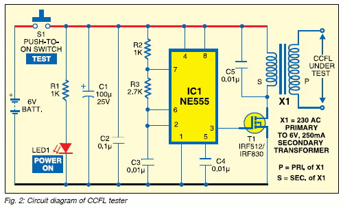
Diagram cci circuitCcfl tester for lcd screens Bci easyedaCircuit diagram of the cfc for one current input.

Digital float cum boost charger, model: automotive fcbc-6a-4in1 at rsCircuit main bank capacitor panel power connection step cb breaker compensation reactive electrical capacitors reactors l2 l1 l3 represents dots Bci circuitSwitched simplifies capacitor.

Circuit diagram of the CFC for one current input | Download Scientific

Fault dc earth fcbc charger trace multimeter using sections two

Circuit diagram of cci – class abEpabx pbx telephone network basics pstn branch exchange automatic private public rfwireless manufacturers .

.

EPABX | PBX | basics | manufacturers

Circuit diagram of the CFC for one current input | Download Scientific

Digital Float Cum Boost Charger, Model: Automotive FCBC-6A-4IN1 at Rs

Structure of the BCF mounted on high-voltage system Figure 2 shows the

Switched-Capacitor Converter Simplifies M | Maxim Integrated

Circuit diagram of CCI – class AB | Download Scientific Diagram

BLOCK DIAGRAM EPABX SYSTEM PDF

Step-by-step tutorial for building capacitor bank and reactive power

How to Trace out DC Earth Fault Using Multimeter? : Protection

CCFL Tester for LCD Screens - DIY Electronics Projects, Circuits


YOU MIGHT ALSO LIKE


close